|
Install Tips
The following is a tutorial on
installation of our most popular model, the YG-101 Swing
Gate opener. Expect to see installation tutorials for
other models as they become available. Note this
tutorial is not a substitute for the manual, read the
manual completely before beginning installation.
This tutorial is divided into
the following sections.
1. Necessary Tools and
Equipment
2. Installation Method
3. Site Preparation
4. Mechanical Installation
5. Wiring the Motors and
Control Box
6. Setup and Tuning
7. Maintenance and
Troubleshooting
1. Necessary Tools and
Equipment
Installing a gate opener is not
an easy job, and is best performed by a professional,
however if you are a serious do-it-yourselfer, this
could be a job for you. You will need some tools before
we get started. You will need standard and phillips
screw drivers, an electric drill, wire cutters and a
wire stripper, a socket set, and access to a welder. If
the bracket parts shipped do not fit your gate because
of the dimensions of your gate, you may also need
equipment to cut and grind metal parts. In some rare
cases you may have to fabricate brackets for your
application.
2. Installation Method
There are basically two ways to
install the YG-101, "push to open", and "pull to open".
The name says it all, either the motors extend pushing
the gate open, or they retract pulling the gate open.
We need to decide first which type of installation this
is. The difference between "push to open" and "pull to
open" is that the gate is mounted on a different side of
the mounting post. for "pull to open", the gate is
mounted inside the posts, while for "push to open", the
motor is mounted inside the posts, and the gate is
mounted on the post face 90 degrees from it. The
illustrations below should help clear things up.
Figure 1
Figure 2
In the illustrations above, the
blue lines represent the gate, and the grey objects are
the gate motors. Taking a look at the enlarged section
may help too. If at anytime this seems unclear you can
email
[email protected]
for help or see our FAQ page here on the website.
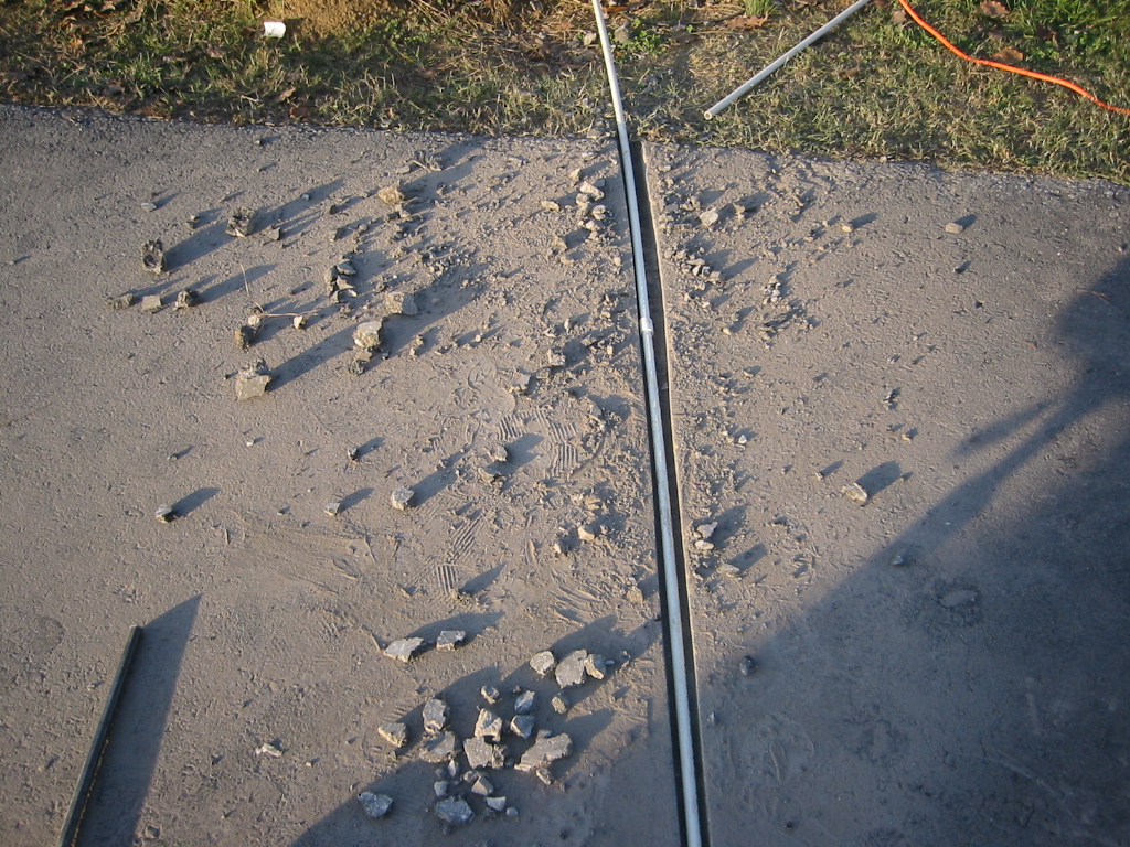
3. Site Preparation
Before we begin,
this tutorial will assume that the gate is mounted to
the mounting posts and swinging freely, there should be
little resistance in the swing of the gate. Since both
motors must be powered, a set of wires from the control
box to both motors will be required. Therefore it is
necessary to dig a shallow trench across the driveway.
If the driveway is paved this will require a masonry saw
and chisel. The YG-101 is powered by 110V/60Hz AC
power, therefore if you have not already done so, wire a
waterproof outlet near the gate following proper safety
standards for your area. If you are not experienced
with this type of wiring or if your area requires it,
hire a professional electrician to perform this as well
as wire in the YG-101 in step 6. Once the gate is
mounted adequately, electrical power is available, and a
trench for the control motors is dug, we are ready to
proceed to step 4
4. Mechanical Installation
Now that the gate
is installed, and power is available, lets install the
motors. First weld part b1 to part b2 as shown:
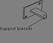
Figure 3
Then mount the assembly b1-b2
on your post according the figure 1 or figure 2
depending on whether yours is a push to open or pull to
open configuration. Verify that the bracket is mounted
level and square with the post. Make sure that both
gate motors are unlocked by turning the keys supplied.
Mount each of the gate opener motors to the bracket
b1-b2 as shown below.
Figure 4
To
install the rear part of the gate opener, insert
shoulder screw and spacer, then tighten with the nut.
Next
open the gate to its maximum position 90 degrees, and
weld bracket b3 onto your gate. Alternatively you can
drill a hole in bracket b3 and bolt it to your gate.
This area really depends on what gate you are using and
how you want to attach it. Some gate may even include
the bracket hole to mount to and bracket b3 will not be
necessary.
Figure 5
To install the front
part, fit the hole in the front part with the hole in
the supporting plate
b3, and push the axle pin into the holes (using your
hands or a hammer), and finally fit the retainer clip.
See Fig.6.
Figure 6
With the gate motors in their
UNLOCKED condition, you should be able to freely move
the gate from the open to the closed position. If the
motion is not as desired, you may have to rework the
position of one or both brackets to obtain the desired
motion. Do not proceed, until the gate can move from
the open to the closed position with the gate motors
attached.
5. Wiring the Motors
OK, now we have the gate
installed, power available, and the gate opener motors
mounted to the gate. We need to next run wires from the
gate opener motors to the location that you plan to
mount the control box. We suggest you mount the control
box inside your property out of direct sunlight and in a
safe location. The control box should also be in an
area where you can easily access it for the tuning
procedure in section 7.
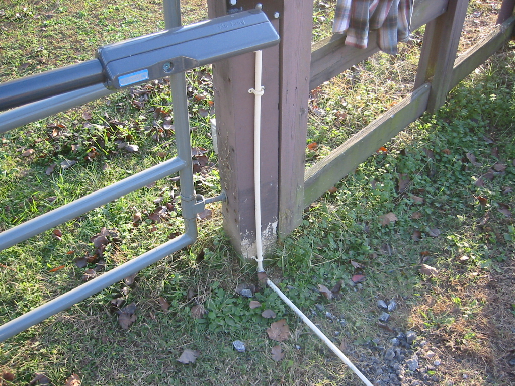
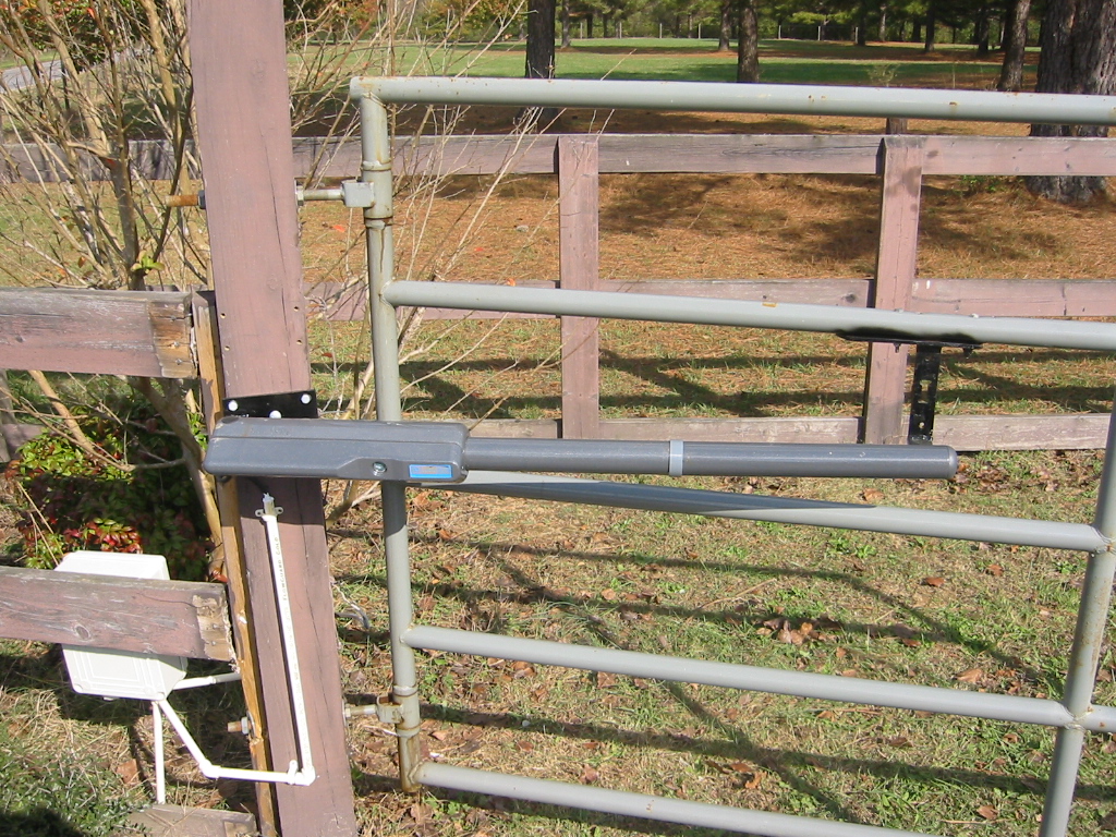
Obtain a quantity of normal
lamp cord gauge 18-3 available at your local Lowe's or
Home Depot. WARNING, use only 18-3 or better wire to
cable your gate motors. Run the wire from the motors to
the control box. It is recommended that you run the
wire in a PVC or other electrical conduit to protect it
from cuts or gouges. You can also run the electrical
cable from the control box to the 110V outlet in this
manner. See the photo below for an example.
Mount the control box by
removing the cover with a phillips screw driver and
screwing through the mounting holes into a mounting
surface like a post or fence. Make sure it is a sturdy
and appropriate surface. You can leave the cover off
for now while we wire the motors.
Wiring
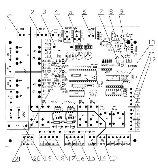
Screw off the two
stainless tapping screws, then remove the cover and
wiring as shown in Fig. 6. WARNING: Follow the
wiring diagram precisely. Failure to do so could cause
damage to the gate opener controller.
You will wire from motor 1,
U,V,W contacts to block 18, contacts U,V,W and from
motor 2 U,V,W to block 16 U,V,W. See table and circuit
diagram below. It does not matter which motor you
decide to be motor 1 and which you designate motor 2.
It is a good idea to use one color wire for U, one for V
and one for W. For instance if you wire contains black,
white, and green then you might use U=Black, V=White,
and W=Green. Just remember to wire them correctly
because mis-wiring could cause DAMAGE to the gate
controller.
|
No.
|
Tag
|
Remark
|
|
1
|
U1
|
No.1 motor: COM/U
|
|
2
|
V1
|
No.1 motor:
V
|
|
3
|
W1
|
No.1 motor:
W
|
|
4
|
U2
|
No.2 motor: COM/U
|
|
5
|
V2
|
No.2 motor:
V
|
|
6
|
W2
|
No.2 motor:
W
|
IMPORTANT SAFTEY
INFORMATION

Installing the YG101
Gate Opener requires wiring of standard AC 110V
electrical lines. This should only be performed by a
trained technician. In some areas, it may be required
that a licensed electrician perform these steps. Mis-wiring
could cause personal injury or DEATH. To prevent the
risk of electrocution, be sure to turn off all power to
the YG101 until installation is complete.
Once the gate openers are
wired to the controller box, we are ready to wire the
control box to your electrical outlet. Using the 18-3
gauge electrical wire, wire a standard grounded plug
(available at Lowe's or Home Depot) to your Gatekeeper
control box using standard electricians wiring
practices. Wire the opposite end of this cable to the
E, N, L contacts of the YG-101 control box. Connect L
to the power or black line, N to the neutral or white
line, and E to the ground line. At this point, we
should be ready to fire it up, plug in the control box,
and turn the locks to the lock position on both gate
motors. If the lock will not turn, then do not force
it, this could cause the key to break. If the lock will
not turn, then it is because the motor is under load,
perhaps the attachment between the motor and the gate is
misaligned and putting it under load, remove the load
then lock the gate motor.
6. Setup and Tuning
Now that
everything is setup, lets allow the gate to learn its
remote controls:
Press the red
learn button on the control board, the LED will turn
on. It will turn off when you press any button on the
transmitter. Press the same button and the LED will
flash with a 2Hz frequency. If the learning process
fails for any reason, the LED will turn off after
flashing for 1 second. If you need to erase the codes,
press and hold the red button on the control board until
the LED stops flashing. After once second, it will
flash again, this indicates that the remote controls
have been erased.
The gate should be
opening and closing with the push of a button now, push
once to open, once to close and pressing the button
while it is moving will cause it to stop.
Now it is very
important that you tune the safety reverse function on
your gate opener.
You must use a
screw driver to rotate the Force Adj. knob. Rotating
clockwise will increase the resistance needed to trip
the safety reverse function. Rotating counter-clockwise
will decrease the resistance. If the gate does not move
when activated, the resistance setting may be too
little. If the gate does not stop when an obstruction
is placed in its path, then the setting may be too
high. Start with just above the minimum value, and tune
it to use the minimum setting for which the gate will
function.
WARNING: Do not
attempt to tune the gate by placing your hand, arm or
other body part in the path of the gate, serious injury
could result. Also placing a heavy immovable object in
the path to test with could cause damage to the gate
opener motors. Instead, place a light object in the
path, preferably something like a chair or trash can
which will be pushed out of the way if the setting is
still too high without causing damage to the gate
motors. Note, this auto reverse function should be
regularly inspected and adjusted if necessary. Now that
the tuning is complete you can replace the cover.
Congratulations,
your new gate opener is installed!
7. Maintenance and
Troubleshooting
Note:
If the gate running direction is not correct, please
change wires .V1 and
W1.or .V2 and W2..
If the wiring between two gates is wrong and the gates
cannot work,
please check the wiring between .U1, V1, W1.and .U2, V2,
W2..
Check
the screw lubricant and add 1# grease regularly.
Keep opener
clean at all times.
If you are still having
trouble, email
[email protected]
for help.
Thanks
The Gatekeeper Team.
|